

Hopper Setup#
This section describes the procedure for configuring the Hopper. The Hopper is the component that automatically feeds parts onto the FlexiBowl® when the level drops below a minimum threshold.
Important
Operating logic
FlexiVision manages the hopper activation logic. It will send the string Hopper;signalnumber;time when it determines activation is necessary.
Note
Prerequisites
Before proceeding, make sure that:
The Hopper has been mechanically installed
The electrical connections have been completed (control signals and power supply)
The FlexiBowl® is already connected
Physical Setup Preparation#
0 |
Remove the calibration grid and restore the initial layout:
|
Accessing the Hopper configuration#
1 |
From the software’s main page, click on |
2 |
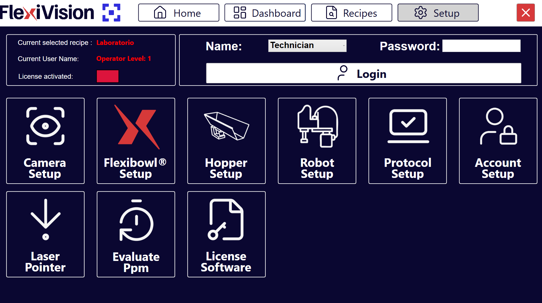
On the SETUP page, locate and click the Hopper Setup icon Setup Page
|
3 |
The Hopper configuration page opens |
Hopper Setup interface overview#
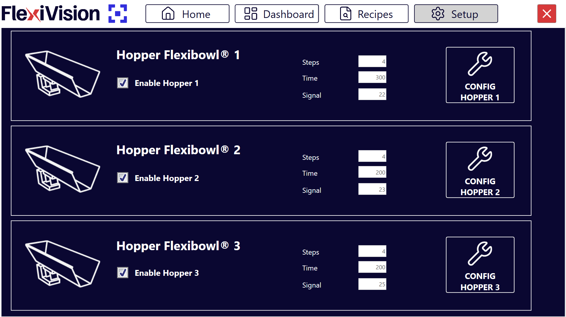
The Hopper Setup page presents several sections for configuring the operating parameters of the various hoppers:
Section |
Description |
|---|---|
Enable Hopper |
Switch to enable/disable use of the Hopper in the system |
Steps |
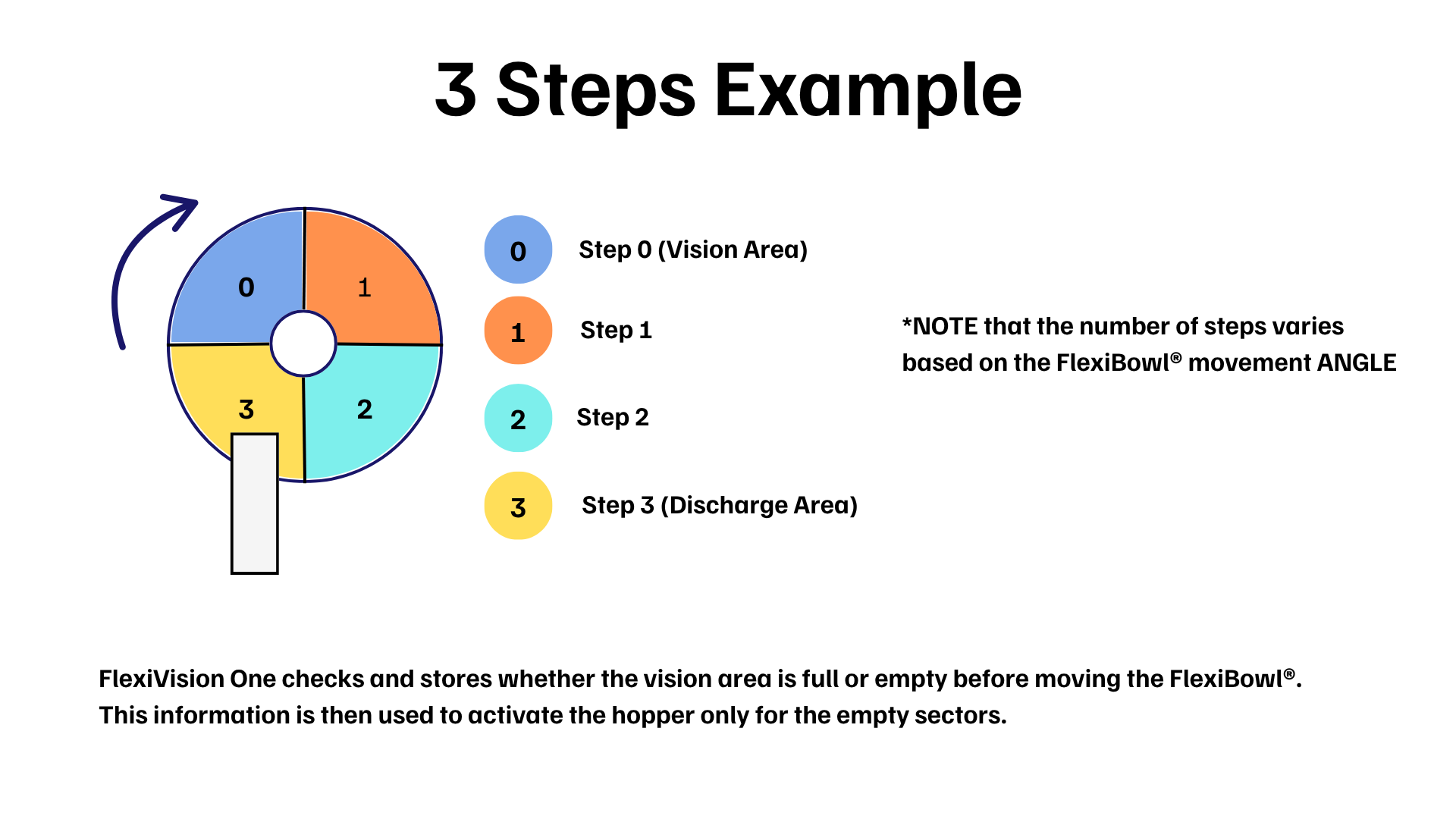
Number of sequences required for the disc section currently in the vision area to arrive under the hopper’s discharge area |
Wizard Steps |
Starts the guided procedure for the automatic calculation of the Steps parameter (see Wizard Steps) |
Time |
Duration of hopper activation in milliseconds |
Wizard Time |
Starts the guided procedure for the automatic calculation of the hopper activation parameters (see Wizard Time) |
Signal |
Digital signal number used to control the Hopper |
Config Hopper |
Button to configure the hopper (to be used next) |
Hopper Configuration#
Hopper configuration allows the automatic replenishment of components on the FlexiBowl® disc to be managed. The system uses vision to determine when the fill level is insufficient and to activate the hopper.
Step 1: Accessing the Configuration#
1 |
Click on Hopper Setup Page
|
2 |
In the Signal field, enter the digital signal number (DO - Digital Output) used to control the Hopper Warning It is essential to enter the correct signal number:
|
3 |
Select the Enable Hopper X checkbox to activate the corresponding hopper. Important Only enable the Hopper if the device is correctly installed |
4 |
Click the Config Hopper X button to access the specific configuration |
Step 2: Defining the Control Area#
In this phase, the portion of the disc that the camera must monitor for discharge is defined.
5 |
Adjust the blue box on screen to frame the area in which components will be detected. |
Tip
For any questions during configuration, refer to the INFO button on the current page.
Step 3: Defining the Threshold Values#
6 |
Click Define Value Hopper Cam Page
|
7 |
Remove all components from the vision area and click the first CAPTURE button. |
8 |
Place the minimum number of components you want to keep in the vision area. If the number drops below this threshold, the hopper will activate. |
9 |
Click the second CAPTURE button. |
10 |
By clicking |
11 |
Remove a few pieces and click |
12 |
Observe the result indicator:
|
 to access the Define Value Hopper Cam page, where the system is taught to distinguish between an empty and a full disc.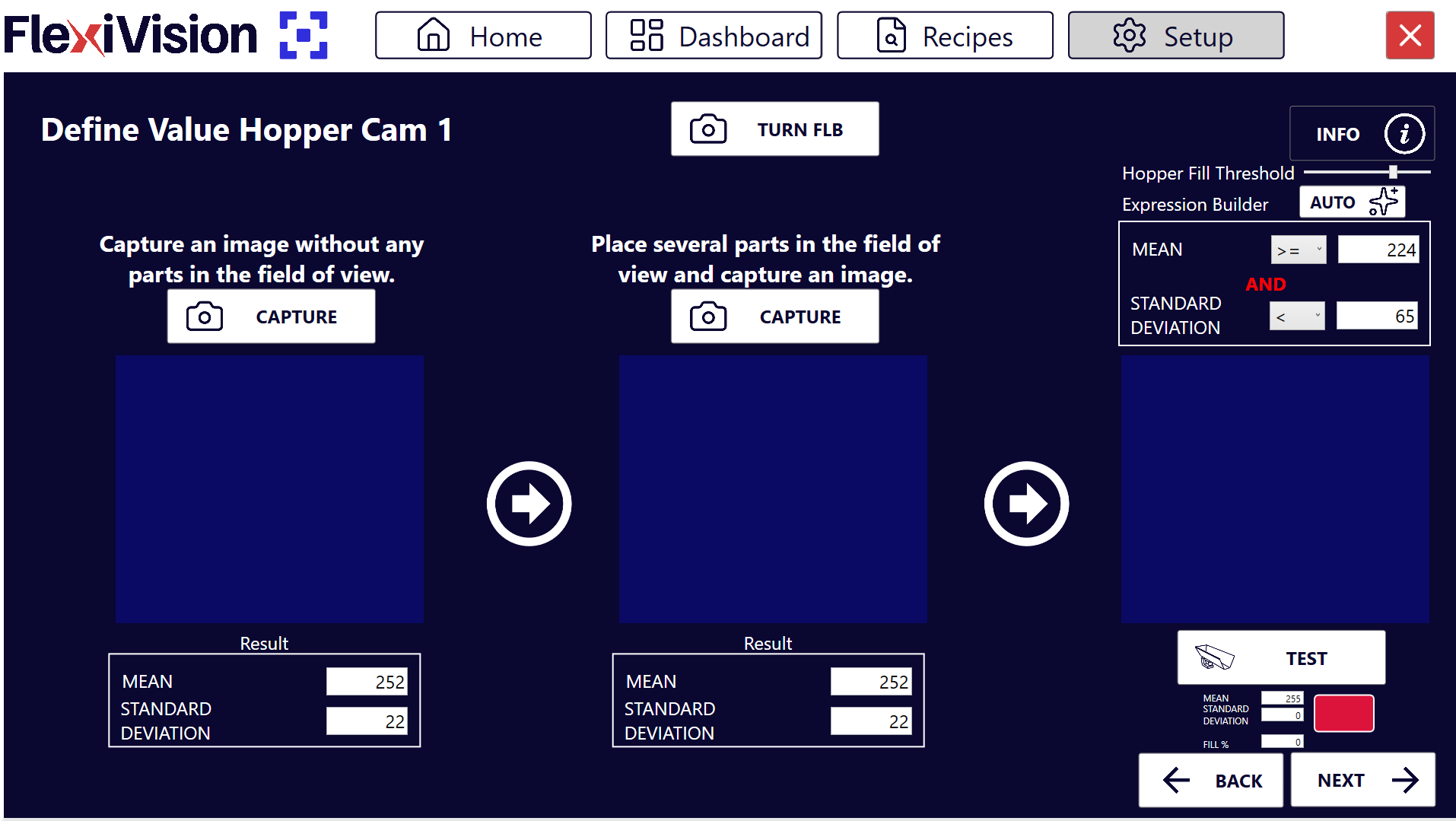
 in the Expression Builder, the system automatically calculates the Mean and Standard Deviation values.
 .
.Note
Hopper Fill Threshold
The Hopper Fill Threshold parameter defines the percentage fill threshold of the vision area below which the hopper automatically activates.
The value of 100% corresponds to the quantity of pieces acquired during the second CAPTURE (full area). Consequently, a threshold of 50% corresponds to half that quantity.
The system automatically sets the initial value to 70%, which represents a good balance for most applications.
Adjusting on the fly
You can adjust the threshold without repeating the acquisition procedure:
To discharge fewer pieces → reduce the percentage (e.g. 50%) and click AUTO
To discharge more pieces → increase the percentage (e.g. 85%) and click AUTO
Tip
For any questions during configuration, refer to the INFO button on the current page.
Step 4: Operating Parameters#
Return to the main Hopper Setup screen to define the mechanical behavior.
Parameter |
Description and Procedure |
|---|---|
Steps |
Number of FlexiBowl® advances (sequences) required to bring the pieces from the vision area to the hopper’s discharge area. Can be set manually or calculated via the Wizard Steps. |
Time |
Hopper activation time in milliseconds. Recommended value: 100 – 1000 ms (Average: 500 ms). Adjust by ±50 ms depending on the desired flow. Can be set manually or calculated via the Wizard Time. |
Tip
The activation time depends not only on the value set, but also on the current volume of components present in the hopper tank. It is essential to maintain a constant load for a uniform flow.
Tip
The Time value is closely linked to the hopper’s load volume:
With a full hopper there will be a greater number of pieces in the discharge area
With a half-full hopper there will be a smaller number of pieces in the discharge area
Important
In general, it is important never to exceed the maximum load of the hopper used.
Wizard Steps: Guided Calculation of the Steps Parameter#
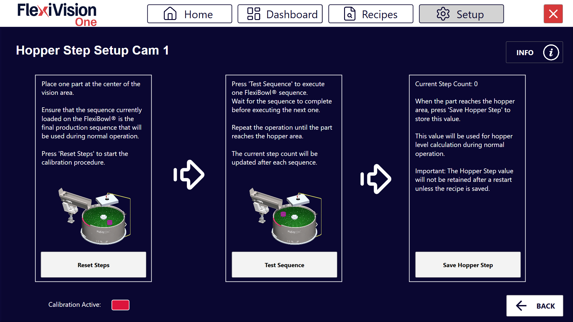
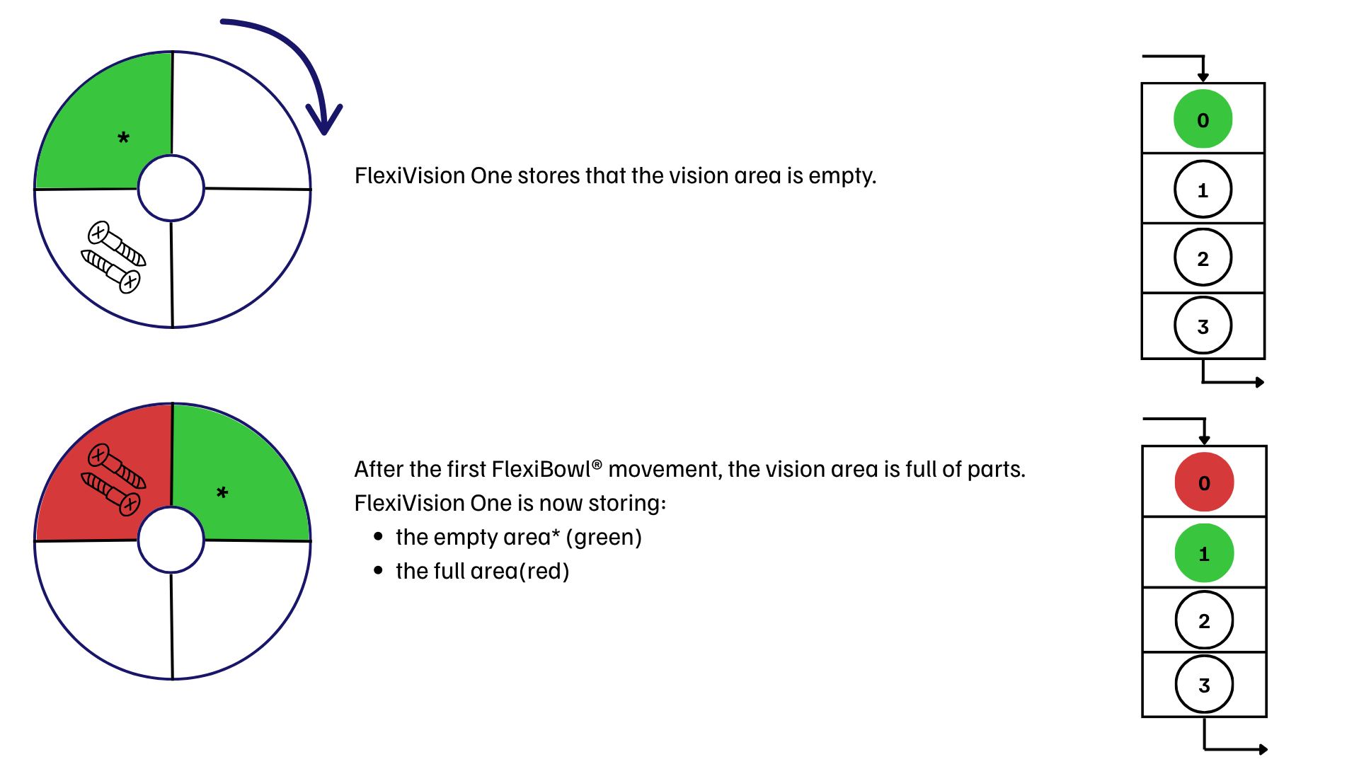
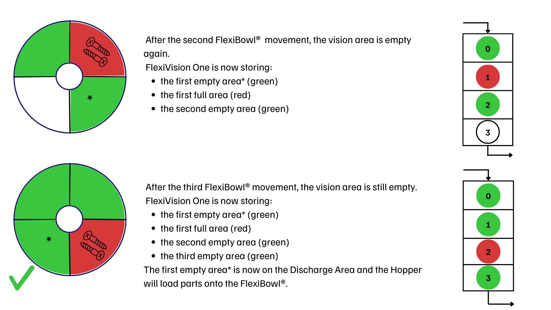
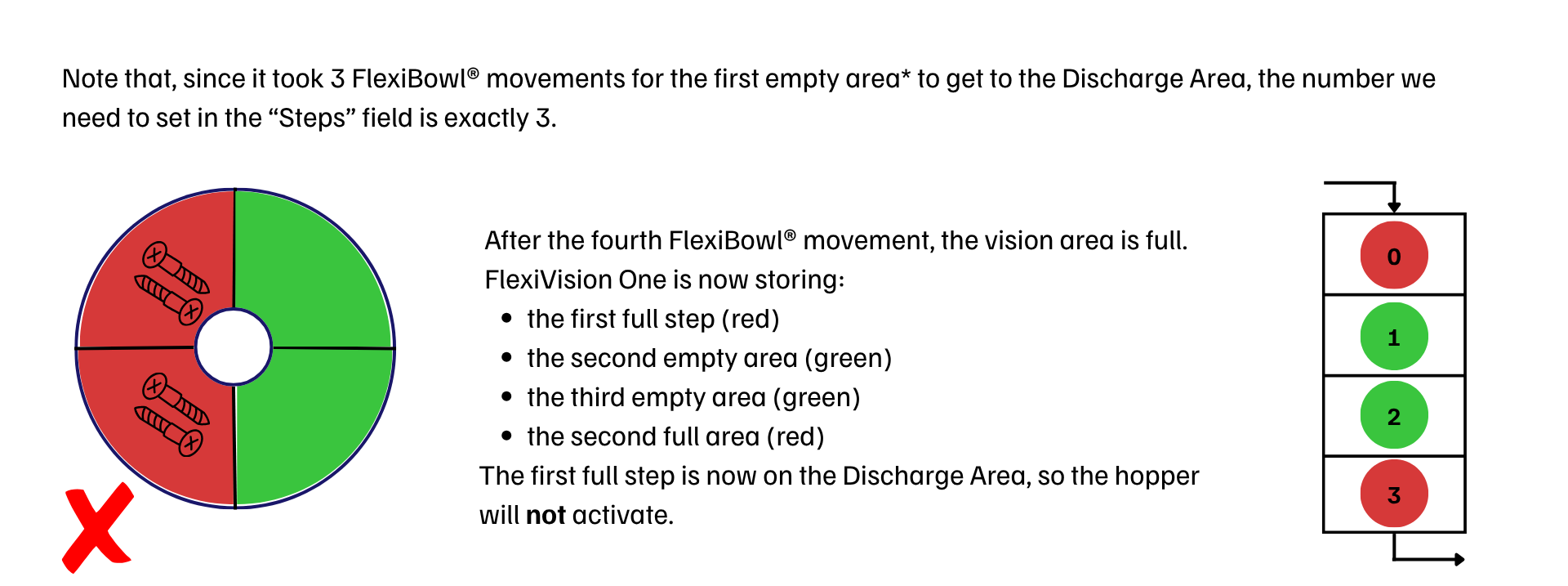
The Wizard Steps guides the operator in calculating the number of sequences required for a piece, positioned in the center of the vision area, to reach the hopper’s discharge area.
Hopper Step Setup Cam X
1 |
Place a single piece in the center of the vision area. Important Make sure that the sequence currently loaded on the FlexiBowl® is the final one, i.e. the same one that will be used in production. A subsequent sequence change would invalidate the calculated value. |
2 |
Click Reset Steps to reset the count and start the calibration procedure. |
3 |
Click Test Sequence to run a single FlexiBowl® sequence. Tip Wait for the sequence to complete before running another one. |
4 |
Repeat the click on Test Sequence until the piece reaches the hopper area. The Current Step Count updates automatically after each sequence executed. |
5 |
When the piece reaches the hopper area, click Save Hopper Step to save the current value as the Steps parameter. |
Warning
The value calculated with the Wizard Steps is not retained after a software restart if the recipe is not saved. Remember to save the recipe at the end of the procedure (see Saving the Configuration).
The Calibration Active indicator shows the status of the calibration in progress:
Color |
Status |
|---|---|
🔴 Red |
Calibration not active / not yet started |
🟢 Green |
Calibration in progress / completed |
Calculating the Steps Parameter#
Wizard Time: Guided Calculation of the Activation Parameters#
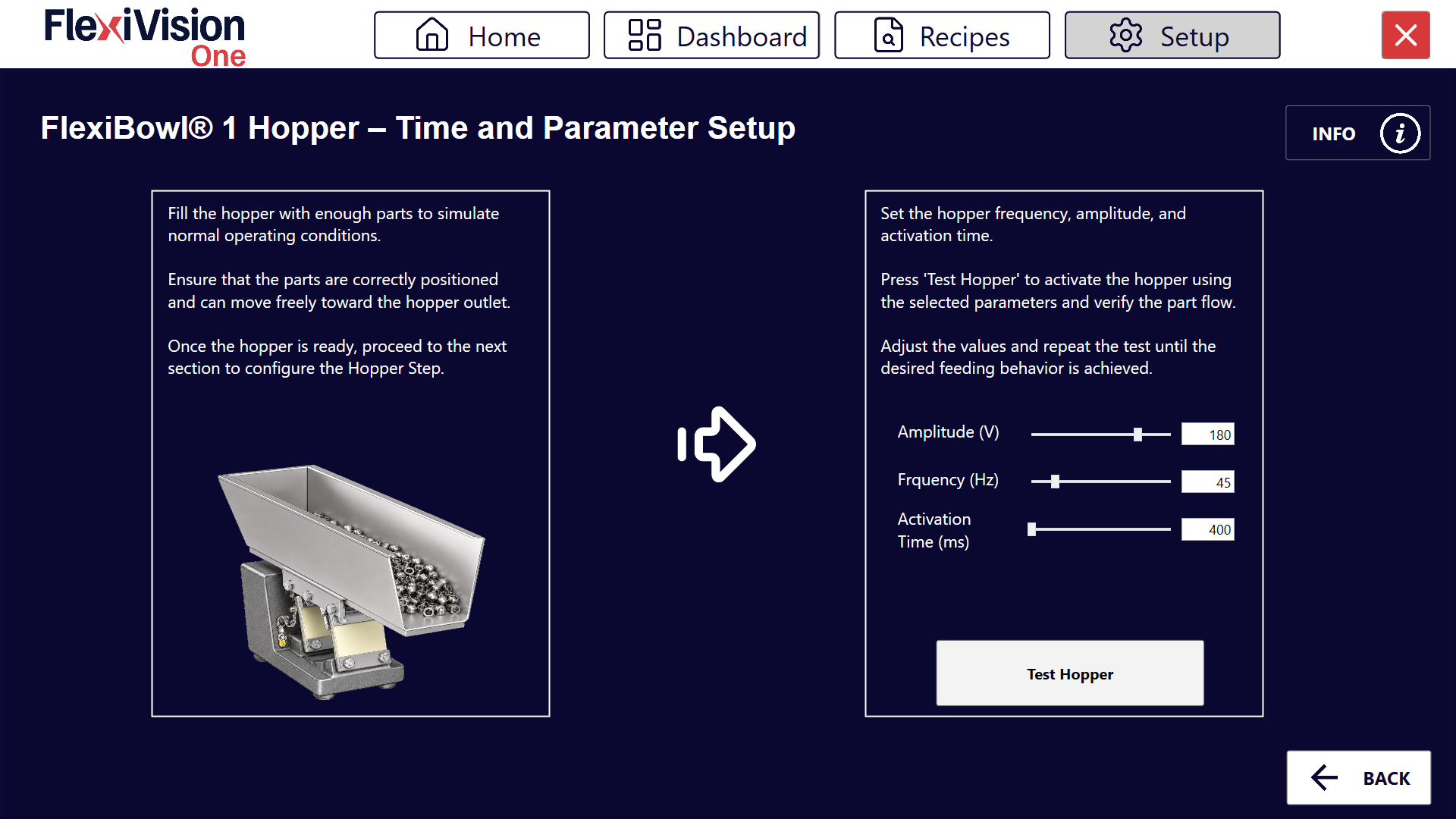
The Wizard Time guides the operator in adjusting the hopper activation parameters (amplitude, frequency and activation time), checking their effect through a direct test on the flow of pieces.
FlexiBowl® X Hopper – Time and Parameter Setup
1 |
Fill the hopper with a sufficient quantity of pieces to simulate normal operating conditions. |
2 |
Check that the pieces are correctly positioned and can move freely toward the hopper outlet. |
3 |
Set the Amplitude (V), Frequency (Hz) and Activation Time (ms) values using the relevant sliders or by entering the value directly in the numeric field. |
4 |
Click Test Hopper to activate the hopper with the set parameters and check the flow of pieces. |
5 |
Adjust the values and repeat the test until the desired feeding behavior is achieved. |
Tip
Proceed with the configuration of the next section (Hopper Step) only once the flow of pieces is satisfactory.
Saving the Configuration#
Warning
Recipe saving mandatory
At the end of the Hopper configuration:
Check that all parameters are configured correctly:
|
|
Return to the main page |
|
Click on |
|
Confirm the save |


IMPORTANT: Any change made is stored ONLY if the recipe is saved correctly before exiting or changing page.
Without saving, all Hopper configurations will be lost when FlexiVision One is closed!
Next steps#
Once the Hopper Setup is complete (or skipped if not present), proceed with: